How does a 3 phase transformer work? 3 phase transformers are the most widely used transformers in our industry, 3 phase transformers are of two types, 3 phase autotransformers and 3 phase isolation transformers, how do they work? Learn how a 3 phase transformer works with this article.
1. What is a 3 phase transformer?
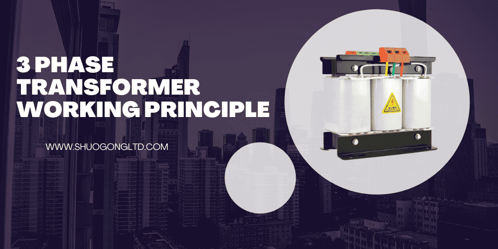
The principle of a 3-phase transformer is actually composed of three single-phase transformers.
A 3-phase transformer consists of three primary coils and three secondary coils, represented as three phases.
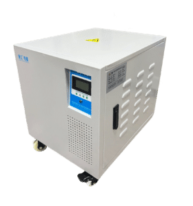
A 3-phase transformer can convert the 3-phase voltage you input into the working voltage required by your equipment, such as converting a 480V input voltage to a 240V output voltage.
3-phase transformers can be used in CNC machine tools, SMT, printing machines, EDM machines, automatic plug-in machines, precision measuring equipment, laser cutting machines, plastic molding machines, medical monitoring systems, PCB drilling machines, laboratory equipment, military instrumentation control Center etc.
2. 3-phase transformer working principle
The 3 phase transformer working principle is based on the principle of electromagnetic induction.
Using electromagnetic induction to convert one alternating voltage into another.
A 3-phase transformer is used to connect an AC source to a grid where the mains voltage and the load voltage are different.
A three-phase transformer is an electrical device used to change the voltage of an AC power source. It consists of two coils wound on a common iron core, connected in series with each other and connected to a load.
The first coil is called the primary winding and the second coil is called the secondary winding. In this circuit, the primary winding acts as a source to convert alternating current to direct current. While the secondary winding acts as a load to convert DC to AC according to its requirements or the voltage and frequency levels required by different types of loads such as motors etc. which are connected to it.
If a three-phase AC source is connected to the primary windings, power is generated on each secondary winding according to the number of turns it has.
When a three-phase AC source is connected to the primary winding, corresponding power is produced on each secondary winding according to its number of turns. The primary winding has more turns and the secondary winding has fewer turns.
The power produced in the primary winding will be equal to the power produced in the secondary winding. Likewise, the power produced by each secondary winding is also equal to the power produced by the corresponding primary winding.
Three-phase transformers can be used to connect AC sources to grids with different supply and load voltages. This difference in voltage is called boosting or bucking, depending on whether the supply voltage is greater or less than the load voltage, respectively.
Three-phase transformers can be used to connect AC sources to grids with different supply and load voltages. This difference in voltage is called boosting or bucking, depending on whether the supply voltage is greater or less than the load voltage, respectively.
3. Steps explain how a step-up/step-down transformer works
The input current of a three phase transformer flows through the primary winding, which has terminals connected at 1/3rd of a cycle apart (for example, if you have an input frequency of 60 Hz then these terminals will be 120 degrees apart).
Due to this arrangement, each terminal carries alternating current with different amplitudes and phases from the other two terminals. Therefore, we can say that three phases are generated through this arrangement.
A 3 phase transformer with identical primary and secondary windings acts as an isolation transformer. An isolation transformer provides galvanic isolation between two circuits.
A three phase transformer with identical primary and secondary windings acts as an isolation transformer. An isolation transformer provides galvanic isolation between two circuits. The difference between a conventional three phase transformer and an isolation transformer is that the latter has no common terminal.
4. 3 phase autotransformer working principle
The circuit diagram of an 3 phase autotransformer is shown in Figure. When the single phase AC supply is connected between A and D terminals and output is taken from C and E terminals, this auto transformer will operate as a step-down transformer.
Because the number of turns in winding between A and D terminal (i.e. primary winding) is more than the number of turns in winding between C and E terminal (i.e. secondary winding).
On the other hand, when the single phase AC supply is connected between B and D terminals and output is taken from C and E terminals, the same auto transformer will operate as a step-up transformer.
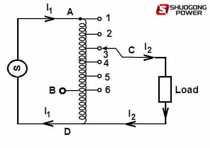
Because the number of turns in winding between B and D terminal (i.e. primary winding) is less than the number of turns in winding between C and E terminal (i.e. secondary winding). We can make small variations in output voltage by taking the output from different tapings of the auto transformer.
5. 3 phase isolation transformer working principle
3 phase Isolation transformer can reduce the capacitance of the primary wiring and secondary wiring. In general, there is an isolating circuit between the primary winding and the secondary winding of the isolation transformer. But if the frequency is high, there will be static interference usually on both sides.
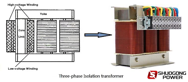
Such interference can be avoided by placing the primary winding and secondary winding of the isolation transformer on different cores. In this way, the capacitance between the two can be reduced. Their positions have certain principles and functions. Concentric placement will cause static shielding, which has high anti-interference.


